Interesting post. Zero point energy could be fairly well understood in the realm of classified physics, but it's not anything we're going to see any time soon. Free energy would doom humanity. Expensive energy applies brakes to growth, teaches people what they're basically here to learn-- that they have to operate within limits.
What is true in the personal and social realm is equally true when applied to our relationship with the natural world. There is a moral if not spiritual component to energy. Taken further into the military realm, the moral failure of humanity in a free energy environment would logically lead to exotic arms production. You really want to see a survivalist with a nasty attitude and a bunch of handguns, in a world of free energy? He'd have all the energy in the world at his disposal, on a planet devoid of water, animals, plants, after the human population explosion. Zero point energy, if available to the public, would equal zero eco-system, zero planet, zero us.
As far as ufos go, I'll take the words of Edgar Mitchell, the late Gordon Cooper and Story Musgrave, three respected astronauts, over any yahoo with compelling but ultimately useless psycho-social theories. If paying heed to the most highly trained observers on the planet is psychological ratcheting, we have a problem here. The condescending attitudes embodied in the dominant epistemologies of our times, ones that pathologize witnesses of events that are poorly understood, says much more about the debunker than the sincere witness. He is a mundane thinker- he is sensitive to social pressure- he is a careerist who toes the line, living a delusion, thinly veiled by a guaze of intellectual arrogance.
The ufo phenomenon demands more open and intense scrutiny, not dismissal. Political deconstructionism is applied to every social/political topic, but this one, and that's a shame, because anyone wishing to approach this topic from this angle will be engaged and enlightened.
Albente, There are some highly credentialed, highly placed individuals who are very interested in the esoteric. Why be ashamed of ufo interest? What happened to you? PM me, if you like.


PeakOil is You
Zero Point Energy (merged)
![]() by threadbear » Sun 10 Jul 2005, 17:44:40
by threadbear » Sun 10 Jul 2005, 17:44:40
-

threadbear - Expert

- Posts: 7577
- Joined: Sat 22 Jan 2005, 04:00:00
![]() by Novus » Wed 13 Jul 2005, 20:38:34
by Novus » Wed 13 Jul 2005, 20:38:34
I did some more research into the antiquities of ZPE. I found this interesting carving from the Hypostyle Hall of Karnak.

What are those things? The Egyptologists do not know. The pot shaped object on the right appears to be a clay battery. Wires coming out of the pot power some type of electrical device.
This carving was found in the Hypostyle Hall which has a little known wonder of engineering. There is a 100 ton stome placed 70 feet in the air on top of the most massive collumns in the world. The stone is still sitting there 3500 years after it was set.

The Egyptologists give the same standard answer of how the Hypostyle hall was built as they do for every other wonder of the ancient world. That is thousands of slaves toiling away on ropes compelled by merciless task masters. Using the sugested techniques of ramps and rigging this stone is impossible even with thousands of slaves.
I beleive the carving above explains the true technique for lifting the stone. The Egyptians had built a harmonic anti-gravity device similar to Ed Leedskalnin's generator. The construction of the Hypostyle Hall was seen as a miracle from Amon Ra and proof that the Pharaoh was a living god. If it was built by slaves how would it be a miricle? It would only seen as a miricle if the Pharaoh and his priests built it themselves. They could have lifted it if they knew about sacred geometry.

The Egyptions weren't the only ones who knew about sacred geometry. It is also mentioned in the bible to perform another miricle of construction. It was writen that Solomon's temple was constructed with sacred knowledge from God. This knowledge was intrusted to just a few stone laborers who became the guild of Masons. The only purpose for the existance of the free masons after the temple was built is to keep this knowledge secret. The guild of Free Masons has been responsible for the construction of all the great stone wonders of Europe since biblical times. The secret of their trade can be seen in their symbol of a compass and square which is used in a process of squaring the circle to calculate the sacred geometry to move the greatest of blocks. Sacred geometry associated with harmonic anti-gravity is the trade secret the Free Masons have been hiding for all these centuries.
This fits another piece of the ZPE puzzel together.
What are those things? The Egyptologists do not know. The pot shaped object on the right appears to be a clay battery. Wires coming out of the pot power some type of electrical device.
This carving was found in the Hypostyle Hall which has a little known wonder of engineering. There is a 100 ton stome placed 70 feet in the air on top of the most massive collumns in the world. The stone is still sitting there 3500 years after it was set.
The Egyptologists give the same standard answer of how the Hypostyle hall was built as they do for every other wonder of the ancient world. That is thousands of slaves toiling away on ropes compelled by merciless task masters. Using the sugested techniques of ramps and rigging this stone is impossible even with thousands of slaves.
I beleive the carving above explains the true technique for lifting the stone. The Egyptians had built a harmonic anti-gravity device similar to Ed Leedskalnin's generator. The construction of the Hypostyle Hall was seen as a miracle from Amon Ra and proof that the Pharaoh was a living god. If it was built by slaves how would it be a miricle? It would only seen as a miricle if the Pharaoh and his priests built it themselves. They could have lifted it if they knew about sacred geometry.
The Egyptions weren't the only ones who knew about sacred geometry. It is also mentioned in the bible to perform another miricle of construction. It was writen that Solomon's temple was constructed with sacred knowledge from God. This knowledge was intrusted to just a few stone laborers who became the guild of Masons. The only purpose for the existance of the free masons after the temple was built is to keep this knowledge secret. The guild of Free Masons has been responsible for the construction of all the great stone wonders of Europe since biblical times. The secret of their trade can be seen in their symbol of a compass and square which is used in a process of squaring the circle to calculate the sacred geometry to move the greatest of blocks. Sacred geometry associated with harmonic anti-gravity is the trade secret the Free Masons have been hiding for all these centuries.
This fits another piece of the ZPE puzzel together.
-

Novus - Intermediate Crude

- Posts: 2450
- Joined: Tue 21 Jun 2005, 03:00:00
![]() by EnergySpin » Wed 13 Jul 2005, 21:09:51
by EnergySpin » Wed 13 Jul 2005, 21:09:51
$this->bbcode_second_pass_quote('', 'c')ompass and square which is used in a process of squaring the circle to calculate the sacred geometry to move the greatest of blocks
By the way, squaring the circle with these tools is a mathematical impossibility. There is an elegant proof from the 19th century. A less formal way to see why it is impossible, goes back to the school formula for the circle circumference. Pi is an irrational number and cannot be produced by any finite operation of segment subdivision.
So ... they might have had Zero Energy devices but there is no way they could have squared the circle

"Nuclear power has long been to the Left what embryonic-stem-cell research is to the Right--irredeemably wrong and a signifier of moral weakness."Esquire Magazine,12/05
The genetic code is commaless and so are my posts.
The genetic code is commaless and so are my posts.
-

EnergySpin - Intermediate Crude
- Posts: 2248
- Joined: Sat 25 Jun 2005, 03:00:00
![]() by J-Rod » Wed 13 Jul 2005, 22:27:26
by J-Rod » Wed 13 Jul 2005, 22:27:26
For some good reads on stuff like the tubes you posted Novus, google around for Zecharia Sitchin. He's written exhaustive works on the accomplishments of ancient man, and all the knowledge that stemmed from Sumeria, as well as tried to tackle the mystery of why civilization seemed to actually regress from the Sumerian times. Nothing dealing with ZPE, more with theories of the origins of humanity. Of course it's not without alot of skeptics, but I've read several of his books, and I found them to be pretty good. Alot of his points come from his own translations of texts, and of course translations can be biased... or maybe google "Annunaki" - "Those who from heaven to Earth came."
http://tinyurl.com/87sa7
http://www.sitchin.com/
I am sure you can find more.
http://tinyurl.com/87sa7
http://www.sitchin.com/
I am sure you can find more.
-

J-Rod - Lignite

- Posts: 375
- Joined: Tue 17 May 2005, 03:00:00
- Location: Northeast Ohio
![]() by threadbear » Thu 14 Jul 2005, 12:32:58
by threadbear » Thu 14 Jul 2005, 12:32:58
Albente, Sorry, a one word rebuttal won't do. Explain why infinite energy on a finite planet, wouldn't be a dangerous thing for humanity. Go ahead. Take your best shot.
-
threadbear - Expert
- Posts: 7577
- Joined: Sat 22 Jan 2005, 04:00:00
![]() by aldente » Thu 14 Jul 2005, 13:36:41
by aldente » Thu 14 Jul 2005, 13:36:41
I am willing to change my point on that. I had my doubts as well to be honest when thinking the process through and came to the conclusion that the existing systems (economic, political etc.) only would abuse ZPE under the premise of their short sightged motifs that they operate under.
-

aldente - Permanently Banned
- Posts: 1554
- Joined: Fri 20 Aug 2004, 03:00:00
Squaring the Circle
![]() by Novus » Thu 14 Jul 2005, 20:31:38
by Novus » Thu 14 Jul 2005, 20:31:38
$this->bbcode_second_pass_quote('EnergySpin', '
')By the way, squaring the circle with these tools is a mathematical impossibility. There is an elegant proof from the 19th century. A less formal way to see why it is impossible, goes back to the school formula for the circle circumference. Pi is an irrational number and cannot be produced by any finite operation of segment subdivision.
So ... they might have had Zero Energy devices but there is no way they could have squared the circle
Well let me introduce you to sacred geometry where you can square the circle and the value of Pi.
This is in a nut shell how you square a circle. Usa a compass and draw any size circle.

Lift up the needle and swing the compass around and draw another circle of the same size. The two circles should intersect at two points. Draw a circle of the same size at each of the points and you should get something that looks like this.

Shade in the four large arcs and you have the surface area of a squared circle.

It is exactly equal to the square of the radius of circle times Pi.

This is how the Eygptians were able to build the Pyramid as a perfect square. Not only is it also the most perfect square ever built, it is also more perfectly aligned to true north then any other building. How? Because they squared the circle. It sould be imposible to aligne the square Pyramid to the circular Earth perfectly but the Egyptians did it to a degree of acturacy we cannot reproduce today. Over the couse of a year the sun will actually trace squared circular path of three sides of the Pyramid in shadow. This is true absolute prefect north.

It is no wonder or suprize to me that the Egyptians could understand the priciples of ZPE and harmonic anti-gravity.
-
Novus - Intermediate Crude
- Posts: 2450
- Joined: Tue 21 Jun 2005, 03:00:00
![]() by Brandon » Fri 15 Jul 2005, 21:07:21
by Brandon » Fri 15 Jul 2005, 21:07:21
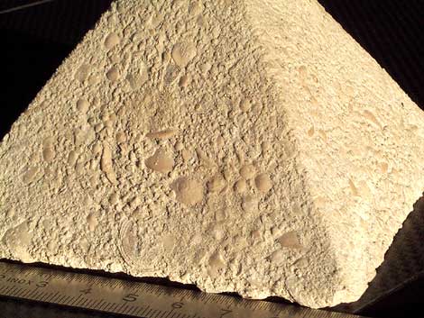
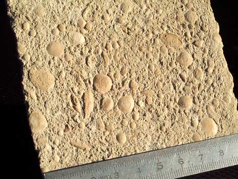
Egyptians, Ed Leedskalnin, and other builders of ancient massive structures likely used an ancient cement. Not ZPE. Not antigravity. The proof is in the analysis of the "stone". Hairs embedded inside the stone. Internal structures not consistent with normal stone.
Download and watch the second video on this page (13.8 MB):
http://www.geopolymer.org/science_archa ... _made.html
On Proving Ancient Megalith Construction:
http://slimebug.home.comcast.net/megaliths.html
Seems reasonable to me.
Download and watch the second video on this page (13.8 MB):
http://www.geopolymer.org/science_archa ... _made.html
On Proving Ancient Megalith Construction:
http://slimebug.home.comcast.net/megaliths.html
Seems reasonable to me.
-
Brandon - Wood
- Posts: 23
- Joined: Tue 28 Jun 2005, 03:00:00
- Location: Tampa, FL
![]() by katkinkate » Sat 16 Jul 2005, 02:36:26
by katkinkate » Sat 16 Jul 2005, 02:36:26
Pity they didn't give a more exact recipe for do-it-yourself stones. Would make great garden borders. You could create your own stonework garden and impress the neighbours.
Kind regards, Katkinkate
"The ultimate goal of farming is not the growing of crops,
but the cultivation and perfection of human beings."
Masanobu Fukuoka
"The ultimate goal of farming is not the growing of crops,
but the cultivation and perfection of human beings."
Masanobu Fukuoka
-

katkinkate - Heavy Crude

- Posts: 1276
- Joined: Sat 16 Oct 2004, 03:00:00
- Location: Brisbane, Australia
![]() by Novus » Sat 16 Jul 2005, 12:09:45
by Novus » Sat 16 Jul 2005, 12:09:45
Ancient cement is nonsence. Ed used Coral which is made out of dead sea creatures. You cannot grind up coral and use cement to reform it and preserve the skeletal structure of the coral. It is like saying you can reform a cow out of hamburger.
The Egyptians carved all their stones. We have proof they were carved because we know where the stones were quarried. They even left some unfinished stones behind such as the Aswan oblisk.


The stone cracked so it was abandoned. If they had ancient cement why didn't they just fix the crack or bother carving the stone in the first place?
$this->bbcode_second_pass_quote('', 'A')ncient cement avoids a timeline violation because it is fully capable of participating in construction of the Trilithon. The natural progression of knowledge is maintained because our knowledge of the physics of lifting has advanced from ancient times as would be expected. Today we can lift and precisely place far more cement than ancient man by using machines that have far less capability than NASA's crane. Hoover Dam is proof.
The Egyptians carved all their stones. We have proof they were carved because we know where the stones were quarried. They even left some unfinished stones behind such as the Aswan oblisk.
The stone cracked so it was abandoned. If they had ancient cement why didn't they just fix the crack or bother carving the stone in the first place?
$this->bbcode_second_pass_quote('', 'A')ncient cement avoids a timeline violation because it is fully capable of participating in construction of the Trilithon. The natural progression of knowledge is maintained because our knowledge of the physics of lifting has advanced from ancient times as would be expected. Today we can lift and precisely place far more cement than ancient man by using machines that have far less capability than NASA's crane. Hoover Dam is proof.
Jim Solley obviously has a problem that the ancients could create wonders modern man can't. So he writes a big long article devoid of facts and rife with untruth to belittle the achievements of the ancients.
-
Novus - Intermediate Crude
- Posts: 2450
- Joined: Tue 21 Jun 2005, 03:00:00